


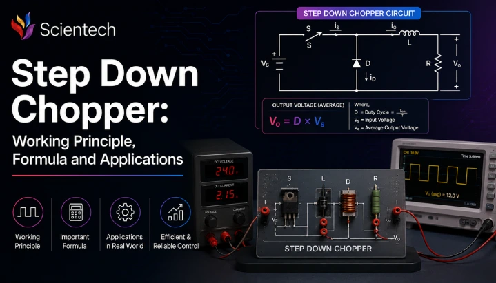
TL;DR
- This blog is for engineering students, GATE aspirants, and freshers who want a clear, exam ready understanding of what a step down chopper is and how it works.
- A step down chopper converts a fixed DC input voltage into a lower, controllable DC output voltage by switching a semiconductor device ON and OFF at high speed.
- The average output voltage depends entirely on the duty cycle, given by the formula Vo = δ × Vs, where δ is ratio of ON time to total switching time.
- Modern step down choppers commonly use MOSFETs, IGBTs, and increasingly GaN or SiC devices instead of the thyristors shown in older textbook circuits. They are used in applications ranging from EV power electronics to switched-mode power supplies and DC-DC converters inside mobile chargers.
- Understanding this topic pays off directly in GATE Electrical Engineering, SSC JE, and power electronics interview rounds, and it opens doors to *one of the most valuable specializations* in modern power electronics.
A step down chopper is a power electronic circuit that converts a fixed DC voltage into a lower, controlled DC voltage using high speed switching rather than resistive dissipation. It is also known as a buck converter or buck chopper, and it forms one of the most fundamental building blocks in power electronics, DC motor control, and many electric vehicle power conversion systems. This guide covers working principle, output voltage formula, circuit behavior under resistive and inductive loads, and real world applications of step down chopper, with particular attention to how modern power electronics technology has evolved.
Also Read,
- AI Projects Engineering Students Can Build for Placements
- Drone Delivery in Last Mile Logistics: Future, Benefits & Challenges
- Wireless Sensor Network (WSN): Architecture & Working
What Is a Step Down Chopper?
A step down chopper is a DC to DC power electronic converter that reduces a fixed DC input voltage to a lower, controlled DC output voltage. It achieves this by rapidly switching input supply ON and OFF using semiconductor devices such as MOSFETs or IGBTs. By controlling the amount of time the switch remains ON (known as duty cycle), average output voltage can be adjusted to the desired level.
Also known as a buck chopper or buck converter, a step down chopper provides efficient voltage control without wasting excess energy as heat. Unlike linear voltage regulators, which dissipate surplus voltage as heat, a step down chopper transfers energy efficiently through high speed switching, often achieving efficiencies of more than 90%.
Because of its high efficiency and precise voltage regulation, a step down chopper is widely used in DC motor speed control, battery powered systems, electric vehicles, renewable energy systems, switched mode power supplies (SMPS), and industrial automation where a lower DC voltage is required from a higher DC source.
Working of Step Down Chopper: Core Principle
To understand working of step down chopper circuits, picture a simple setup with four elements: a fixed DC source, a switching device (chopper itself), a load, and sometimes an inductor with a freewheeling diode if load is inductive in nature.
How Switching Action Produces a Lower Voltage
When the switch is turned ON, full source voltage appears directly across the load. When the switch is turned OFF, the load sees no voltage from the source at all. This ON-OFF cycle repeats continuously at a fixed frequency, usually somewhere between a few hundred hertz and several hundred kilohertz depending on application.
Because switching happens so fast, load does not experience sharp ON-OFF pulses individually. Instead, it responds to the average value of that pulsing voltage. If the switch stays ON for 70 percent of each cycle and OFF for the remaining 30 percent, the load effectively sees about 70 percent of source voltage as its average output. This ratio of ON time to total cycle time is called duty cycle, and it is the single most important control variable in any chopper circuit.
Working of Step Down Chopper with Resistive (R) Load
With a purely resistive load, behavior is straightforward. During the ON period, load voltage equals source voltage, and load current flows in direct proportion to that voltage, following Ohm’s Law. During the OFF period, both load voltage and load current drop to zero immediately, since there is no inductance to store energy and keep current flowing.
This creates a simple rectangular voltage waveform and a matching rectangular current waveform. The load essentially switches between full power and zero power in step with the chopper.
Working of Step Down Chopper with Inductive (RL) Load
Real world loads like DC motor armatures are rarely purely resistive. They have inductance, and inductance resists sudden changes in current. This is where a freewheeling diode becomes essential.
When the switch is ON, current builds up gradually in load, rising toward its steady value but usually not reaching it before switch turns OFF again, since ON time is deliberately kept short relative to load’s time constant. When the switch turns OFF, the source is disconnected, but the inductor does not allow current to stop instantly. Instead, built up current continues flowing through the freewheeling diode, gradually decaying until the switch turns ON again.
This behavior produces two distinct operating modes:
Continuous conduction mode: When load inductance is large enough, current never actually reaches zero between switching cycles. It simply rises and falls within a band, always staying above zero. Most practical motor drives and EV controllers are designed to operate in this mode because it gives smoother torque and less electrical stress on components.
Discontinuous conduction mode: When load inductance is small, stored energy runs out before the next ON period begins, and current touches zero and stays there for a portion of the cycle. This mode causes more voltage and current ripple, which is generally avoided in precision applications but can occur at light loads.
Step Down Chopper Formula and Derivation
The mathematics behind a step down chopper is refreshingly simple once you understand switching behavior described above. This makes it a favorite numerical topic in GATE and other competitive exams.
Defining Duty Cycle
The duty cycle, denoted by δ (or sometimes α), is defined as:
δ = Ton / T
Where:
- Ton = time for which switch remains ON during one cycle
- T = total time period of one switching cycle (Ton + Toff)
The duty cycle always lies between 0 and 1. A duty cycle of 0.5 means switch is ON for exactly half of each cycle.
Average Output Voltage Formula
Since load only receives source voltage during ON period and receives zero (or a freewheeling path) during OFF period, average output voltage over one full cycle works out to:
Vo(avg) = δ × Vs
Where:
- Vo(avg) = average output (load) voltage
- Vs = fixed DC source voltage
- δ = duty cycle
This single formula explains why the step down chopper is such a versatile device. By simply adjusting δ from 0 to 1, you can vary output voltage anywhere from 0 volts up to full source voltage, without ever exceeding it. That upper limit is precisely what makes it a “step down” device rather than a step up one.
Average Output Current
For a resistive load, once you know average output voltage, finding average output current is a direct application of Ohm’s Law:
Io(avg) = Vo(avg) / R = (δ × Vs) / R
Worked Example
Consider a step down chopper operating from a 400 V DC supply at a switching frequency of 1 kHz. If the required average output voltage is 250 V, find ON time of switch in each cycle.
Given: Vs = 400 V, Vo = 250 V, f = 1 kHz
First, find duty cycle: δ = Vo / Vs = 250 / 400 = 0.625
Next, find total time period: T = 1 / f = 1 / 1000 = 1 millisecond
Finally, find ON time: Ton = δ × T = 0.625 × 1 ms = 0.625 milliseconds
This means the switch needs to stay ON for 0.625 milliseconds out of every 1 millisecond cycle to deliver an average output of 250 V from a 400 V source.
Circuit Components: From Thyristors to GaN and SiC
Older textbooks built classic step down chopper circuits around a force commutated thyristor (SCR), since thyristors were dominant high power switching devices when chopper theory was first formalized for DC motor drives and traction applications. That explains why so many derivations you will find still reference thyristor conduction and commutation circuits.
In practice, most step down choppers built and deployed today do not use thyristors at all. The switching device has shifted first to power BJTs, and far more commonly now to power MOSFETs and IGBTs, both of which switch faster, need simpler drive circuits, and do not require extra commutation circuitry that thyristors demand. IGBTs remain standard choice for medium and high power applications like traction drives, while MOSFETs dominate lower voltage, higher frequency designs such as mobile chargers and point of load converters on circuit boards.
A more significant shift by 2026 is the growing adoption of wide bandgap semiconductor devices, specifically Gallium Nitride (GaN) and Silicon Carbide (SiC), in place of conventional silicon switches. These materials have a much wider bandgap than silicon, roughly 3.3 to 3.4 electron volts compared to silicon’s 1.1 electron volts, which lets them handle higher voltages, higher temperatures, and much faster switching speeds. Well-designed wide-bandgap converters can achieve efficiencies of up to around 98% in optimized designs while reducing switching losses and enabling smaller passive components compared with conventional silicon-based designs.
For a student building intuition, essential components of any step down chopper circuit remain consistent regardless of which switching device is used:
- Switching device: Controls when source connects to load. Could be an SCR in an older textbook diagram, or a MOSFET, IGBT, GaN, or SiC device in a modern design.
- Inductor: Stores energy during ON period and releases it during OFF period, smoothing current flow to load.
- Freewheeling diode: Provides a path for inductor current to keep flowing when the switch turns OFF, protecting the switching device from voltage spikes.
- Filter capacitor: Smooths out voltage ripple at output, especially important when a low pass filter stage is added after basic chopper circuit.
- Control circuit: Generates switching signal, typically using pulse width modulation (PWM), and adjusts duty cycle based on feedback from output.
Takeaway: underlying formula and working principle of a step down chopper have not changed since the thyristor era, but switching hardware has, and GaN and SiC devices are now driving the next leap in efficiency and compactness.
Step Down Chopper vs Step Up Chopper
Students frequently confuse step down and step up choppers in exams, so a direct comparison helps clarify distinction.
| Parameter | Step Down Chopper (Buck) | Step Up Chopper (Boost) |
| Output voltage | Always less than input voltage | Always greater than input voltage |
| Also known as | Buck converter | Boost converter |
| Inductor position | In series with load | In series with source |
| Energy storage element | Charges during ON, discharges to load during OFF | Charges during ON, releases to load during OFF through diode |
| Typical formula | Vo = δ × Vs | Vo = Vs / (1 − δ) |
| Common applications | DC motor speed control, battery charging, EV auxiliary supplies | Regenerative braking, solar MPPT systems, voltage boosting for LED drivers |
| Duty cycle range for useful output | 0 to 1 | 0 to close to 1 (approaches infinity in theory as δ nears 1) |
Advantages and Disadvantages of Step Down Chopper
Understanding both sides of this circuit is important, not just for exams but for real design decisions.
main advantages include high efficiency compared to resistive or linear voltage control methods, smooth and stepless control of output voltage simply by varying duty cycle, compact circuit design since bulky rheostats are eliminated, faster dynamic response to load changes, and lower heat generation since switching device spends most of its time either fully ON or fully OFF, minimizing power dissipation in switch itself.
disadvantages are equally worth knowing. Switching action introduces voltage and current ripple at output, which usually requires additional filtering. High speed switching can generate electromagnetic interference (EMI) that may affect nearby sensitive electronics if not properly shielded. switching devices themselves face voltage and thermal stress, particularly during turn off transients, and control circuitry adds complexity compared to a simple resistive controller.
Applications of Step Down Chopper in India
applications of step down chopper circuits in India have grown substantially with push toward electric mobility and renewable energy, making this a genuinely practical topic rather than a purely theoretical one.
Electric vehicle drivetrains: Step down choppers regulate power delivery from battery pack to traction motor controller and to low voltage auxiliary systems like lighting, infotainment, and battery management system. With India’s continued push toward electric mobility and domestic manufacturing including dedicated charging infrastructure funding, and continued support through PLI Scheme for automotive components, demand for engineers who understand buck converter design is rising sharply across two wheeler, three wheeler, and passenger EV manufacturers.
Traction and railway systems: Indian Railways and metro systems use chopper based control for DC traction motors, replacing older rheostatic control that wasted enormous amounts of energy as heat. Step down choppers allow smoother acceleration, regenerative braking compatibility, and significant energy savings across the network.
Battery charging systems: From lithium ion battery packs in EVs to lead acid batteries in UPS systems, step down choppers regulate charging voltage precisely, which is critical for battery life and safety.
Telecommunication power supplies: Telecom towers and data centers across India rely on step down chopper based DC DC converters to deliver stable, regulated voltage to sensitive electronic equipment from higher voltage DC busbars.
Renewable energy systems: Solar power installations use step down choppers as part of charge controllers to safely regulate variable panel output voltage into a stable charging voltage for battery storage systems.
Industrial motor drives: Manufacturing units across India continue to use chopper based DC motor drives for conveyor systems, cranes, and material handling equipment where precise speed control is essential.
Career and Exam Relevance for Indian Students
Power electronics, and step down chopper theory specifically, is not just an academic topic. It has direct career weight for engineering students in India.
GATE Electrical Engineering: Chopper circuits, including step down chopper derivations and numerical problems, appear consistently in the Power Electronics section of GATE EE. Questions typically test duty cycle formula, average voltage and current calculations, and conduction mode identification (continuous versus discontinuous), so this topic is high yield preparation time relative to how often it is tested.
SSC JE and RRB JE: Junior Engineer exams for electrical trades frequently include chopper and DC DC converter questions under power electronics and basic electrical machines sections, making this a core topic rather than an optional one.
Career paths and salary potential: Power electronics has become one of more lucrative specializations within Indian electrical engineering. Entry level electrical engineering roles typically start in range of ₹3 to ₹6 LPA, but professionals who specialize specifically in power electronics for EVs and grid systems can move into a ₹6–20 LPA range as they gain experience, particularly at Salaries vary depending on experience, employer, and specialization, with power electronics remaining one of the fastest-growing domains within electrical engineering.
depending on position and grade, along with long term stability PSU careers are known for.
Students aiming for roles in EV powertrain design, renewable energy integration, or power supply design at companies working on semiconductor based power systems will find that a solid grasp of chopper fundamentals, including step down chopper working and formulas, forms foundation for everything more advanced they will study later, including multilevel converters, inverters, and motor drive control algorithms.
Conclusion
A step down chopper takes a fixed DC voltage and delivers a lower, precisely controlled DC voltage by switching a semiconductor device on and off at high speed, with average output governed by simple formula Vo = δ × Vs. working principle stays consistent whether load is resistive or inductive, though inductive loads require a freewheeling diode and can operate in either continuous or discontinuous conduction mode. While older textbook circuits are built around thyristors, real world step down choppers today run on MOSFETs, IGBTs, and increasingly GaN and SiC devices, which is pushing efficiency well above 98 percent in modern designs. From EV drivetrains and battery charging systems to telecom power supplies and industrial motor drives, this circuit sits at the center of India’s electric mobility and renewable energy expansion, and it remains one of highest yield topics for GATE, SSC JE, and RRB JE preparation. Students who build a strong foundation here set themselves up well for power electronics specializations offering excellent long-term career opportunities in power electronics and energy systems
FAQs
A step down chopper is an electronic circuit that takes a fixed DC voltage and produces a lower, adjustable DC voltage by rapidly switching source on and off. It is commonly called a buck converter and is widely used to control DC motor speed and regulate battery charging voltage.
Average output voltage of a step down chopper is given by Vo = δ × Vs, where δ is duty cycle (ratio of ON time to total switching period) and Vs is fixed DC source voltage. This formula is the basis for nearly all numerical problems on this topic.
A freewheeling diode provides a path for current to keep flowing through an inductive load when the main switch turns OFF. Without it, sudden collapse of current through an inductor would generate a dangerous voltage spike that could damage the switching device.
A step down chopper (buck converter) always produces an output voltage lower than input, while a step up chopper (boost converter) always produces an output voltage higher than input. Their inductor placement and formulas also differ significantly.
Most modern step down choppers use power MOSFETs or IGBTs rather than thyristors shown in older textbook circuits. High performance designs are increasingly moving toward GaN and SiC wide bandgap devices, which allow faster switching and significantly higher efficiency.
Yes, step down chopper theory is a regularly tested topic in the Power Electronics section of GATE EE, along with SSC JE and RRB JE exams. Questions usually focus on duty cycle formula, average voltage and current calculations, and identifying continuous versus discontinuous conduction modes.