


TL;DR
- This blog is for engineering students, freshers, and GATE/SSC JE/RRB JE aspirants who want to understand how an optical fiber communication system actually works, not just memorize its block diagram.
- An optical fiber communication system sends information as pulses of light through a glass fiber instead of electrical signals through copper wire, which is why it can carry far more data with far less loss.
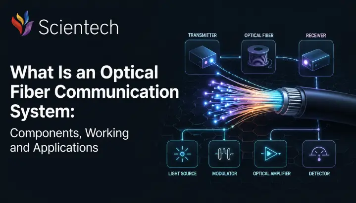
- The system has three core building blocks: a transmitter that converts electrical signals to light, an optical fiber that carries light, and a receiver that converts light back into electrical signals.
- A single worked numerical example on power budget and attenuation is included so you can see exactly how engineers calculate whether a fiber link will work over a given distance.
- The blog closes with India specific context on BharatNet and telecom industry, GATE exam relevance, and realistic career and salary information for students entering this field.
An optical fiber communication system is a method of transmitting information using pulses of light sent through a thin strand of glass or plastic fiber, instead of electrical signals sent through copper wire. It forms the backbone of modern telecommunication networks, carrying everything from phone calls and broadband internet to data center traffic, over distances ranging from a few meters to thousands of kilometers.
This technology matters more today than it ever has. India’s internet backbone, 5G rollout, and even AI data centers now being built around the world all depend on optical fiber to move enormous amounts of data quickly and reliably. For engineering students, especially those preparing for GATE or PSU recruitment exams, understanding optical fiber communication systems is not optional. It is an important topic in electronics and communication engineering and can appear in questions related to optical-fiber propagation, attenuation, and related concepts.
This blog breaks the topic down step by step. Whether you call it an optical fiber communication system or a fiber optical communication system, underlying concepts are the same, and you will learn what it is, how each of its components works, why light is used instead of electricity, and how a real fiber link is designed using a worked numerical example. We will also cover single mode versus multimode fiber, real world applications, India’s fiber optic landscape, and what this topic means for your exams and career.
Also read,
- Drones in Renewable Energy: Solar & Wind Inspection Guide
- Drones in Renewable Energy: How Solar Farm and Wind Turbine Inspection
- BVLOS Drone Operations: What They Are, How They Work, and Why They
What Is an Optical Fiber Communication System?
Think about shouting a message down a long hallway versus writing it on paper and having it carried by hand. Sound weakens and gets distorted by echoes and noise as it travels. A written message stays exactly as clear at the end of the hallway as it was at the start. An optical fiber communication system works on a similar idea, except instead of paper, it uses light, and instead of a hallway, it uses a hair thin strand of glass called an optical fiber.
In a traditional electrical communication system, information travels as electrical current through a copper wire. Copper wires lose signal strength quickly, pick up electromagnetic interference from nearby power lines and machinery, and cannot carry very much data before quality drops. An optical fiber communication system solves all three problems at once. It converts electrical signals into light pulses, sends those light pulses through a glass fiber, and converts them back into electrical signals at the other end.
The result is a communication system that can carry more data, over longer distances, with far less signal loss and virtually no interference from electrical noise. This single advantage is why fiber optic cables have replaced copper as backbone of internet, telephone, and cable television networks worldwide, including across India’s rapidly expanding broadband infrastructure.
How Does an Optical Fiber Communication System Work?
Picture a torch inside a curved, mirror lined tube. Even if you bend the tube, light bounces off mirrored walls again and again and eventually reaches the other end. It never leaks out through the sides because the mirror keeps reflecting it back inward. This is almost exactly how light travels through an optical fiber, except instead of a mirror, fiber uses a clever difference in glass density to bounce light along its core.
At the transmitter end, your data (a phone call, a video, a webpage) starts out as an electrical signal. This electrical signal drives a light source, usually a laser diode or an LED, which switches on and off (or varies in intensity) extremely fast to represent data as light pulses. These pulses enter optical fiber and travel down its core, reflecting internally off boundary between core and surrounding cladding layer, a phenomenon called total internal reflection.
As light travels, it gradually loses some strength due to absorption and scattering within glass. Over very long distances, optical amplifiers or repeaters boost signal back to its original strength without needing to convert it back to electricity first. At the receiving end, a photodetector senses incoming light pulses and converts them back into an electrical signal, which is then amplified and processed to recover original data.
Total Internal Reflection: Physics Behind Fiber
Optical fiber has two main layers: an inner core and an outer cladding. The core is made of glass with a slightly higher refractive index than cladding. When light traveling through a denser core hits a boundary with less dense cladding at a shallow enough angle, it reflects entirely back into the core instead of escaping. This is total internal reflection, and it repeats thousands of times per kilometer as light zigzags its way through fiber.
This is why quality of glass and precision of core to cladding refractive index difference matter so much in fiber manufacturing. A poorly made fiber lets light leak out at every bend, causing high signal loss. A well made fiber, like ones used in telecom grade cables today, loses as little as 0.2 dB of signal strength per kilometer at certain wavelengths, which is remarkably efficient over long distances.
Core Components of an Optical Fiber Communication System
Every optical fiber communication system, no matter how large or small, is built from three essential blocks: transmitter, optical fiber (transmission medium), and receiver. Understanding the exact role of optical fiber in communication system design is what separates a surface level answer from a strong one in interviews and exams. Around these three, several supporting components keep the signal clean and strong over distance. Let’s go through each one way a mentor would, building intuition before terminology.
Transmitter
The transmitter is the starting point of the system. Its job is simple to state but precise in execution: take electrical input signal and turn it into an equivalent light signal that can enter fiber.
The transmitter has two main parts. The drive circuit takes incoming electrical data and shapes it into the exact form needed to control the light source. light source itself, typically a laser diode (LD) or a light emitting diode (LED), then produces actual light pulses. Laser diodes are preferred for long distance, high speed links because they produce a narrow, focused beam of a single wavelength, which suffers less distortion over distance. LEDs are cheaper and simpler, so they are commonly used for shorter links like local area networks, where extreme distance and speed are not priority.
A helpful analogy: think of light source as a very precise, very fast blinking torch. Every blink pattern represents a piece of your data, encoded so precisely that millions of these blinks happen every second.
Optical Fiber (Transmission Medium)
optical fiber itself is a channel that carries light from transmitter to receiver. Physically, the glass fiber itself typically has a cladding diameter of about 125 µm, while the protective coating commonly brings the overall coated fiber diameter to about 250 µm.
A fiber optic cable is built in layers, much like a pencil. At the very center is the core, the pathway through which light actually travels. The surrounding core is cladding, a layer of glass with a lower refractive index that reflects light back into core through total internal reflection. Around cladding sits a buffer coating, a protective layer that shields delicate glass from moisture and physical damage. Finally, an outer jacket provides mechanical protection and is color coded so technicians can quickly identify cable type, yellow typically indicates single mode fiber, while orange or aqua indicates multimode fiber.
Receiver
At the far end of fiber, the receiver has the opposite job of transmitter: convert incoming light pulses back into an electrical signal that can be understood by phones, computers, or network equipment.
receiver consists of three parts working in sequence. A photodetector, usually a PIN photodiode or an avalanche photodiode, senses incoming light and converts it into a small electrical current. This weak signal then passes through an amplifier to boost it to a usable level. Finally, a signal restorer cleans up the signal, removing noise and distortion picked up during transmission, so original data can be accurately recovered.
Supporting Components
Beyond three core blocks, real world optical fiber communication systems rely on several supporting components to maintain signal quality over distance:
Connectors and splices join fiber segments together with minimal signal loss. Optical amplifiers, most commonly erbium doped fiber amplifiers (EDFAs), boost weakening light signals directly, without ever converting them back to electricity, which makes them far more efficient than old style electronic repeaters. Multiplexers, particularly those used in wavelength division multiplexing (WDM), allow multiple data streams to travel through a single fiber simultaneously by assigning each stream its own wavelength of light, dramatically increasing total data capacity of a single cable.
Why Is Light Used Instead of Electricity?
This is a question every beginner should ask, and the answer reveals why fiber optic communication became so dominant. Electrical signals in copper wire are limited by resistance, which causes heat loss, and by susceptibility to electromagnetic interference from nearby power lines, motors, or radio signals. As data rate increases, these problems get worse, not better.
Light does not have these limitations in the same way. A laser produces light at a single, stable wavelength, unlike sunlight or a bulb, which emit a broad mix of wavelengths and scatter easily. Laser sources typically have a narrow spectral width, which helps reduce chromatic dispersion. However, dispersion in fiber also depends on the fiber properties, operating wavelength, and propagation modes. Glass fiber is also a dielectric material, meaning it does not conduct electricity, so it is completely immune to electromagnetic interference from nearby electrical equipment, something copper cable can never fully achieve.
The result is a medium that can carry vastly more data (higher bandwidth), over much longer distances, with dramatically lower signal loss (attenuation), than any electrical cable of comparable size and cost.
Worked Numerical Example: Calculating a Fiber Link Power Budget
Textbook definitions only take you so far. GATE and university exams frequently test whether you can actually calculate whether a fiber link will function correctly over a given distance. Here is a simplified version of how that calculation works.
Problem: A single mode fiber link operates at a wavelength of 1310 nm and needs to cover a distance of 20 km. fiber has an attenuation of 0.4 dB/km at this wavelength. link includes 2 connector pairs, each with a loss of 0.5 dB, and 3 splices, each with a loss of 0.1 dB. A safety margin of 3 dB is added to account for aging and unpredictable losses. If the transmitter launches with a power of 0 dBm and the receiver requires a minimum of 25 dBm to correctly detect the signal, will this link work?
Step 1: Calculate fiber attenuation loss. Fiber loss = distance × attenuation per km = 20 km × 0.4 dB/km = 8 dB
Step 2: Calculate connector loss. Connector loss = number of connector pairs × loss per pair = 2 × 0.5 dB = 1 dB
Step 3: Calculate splice loss. Splice loss = number of splices × loss per splice = 3 × 0.1 dB = 0.3 dB
Step 4: Add safety margin. Safety margin = 3 dB
Step 5: Calculate total link loss. Total loss = 8 dB + 1 dB + 0.3 dB + 3 dB = 12.3 dB
Step 6: Calculate available power budget. Power budget = transmitter power minus minimum receiver sensitivity = 0 dBm minus ( 25 dBm) = 25 dB
Step 7: Compare total loss against power budget. Since total link loss (12.3 dB) is less than available power budget (25 dB), link works, with a comfortable margin of 25 minus 12.3 = 12.7 dB left to spare.
This kind of calculation is exactly what a telecom engineer does before deploying a fiber link, and it is exactly the kind of numerical problem that shows up in GATE Electronics and Communication Engineering papers under the optical communication section. Understanding each term in this calculation, attenuation, connector loss, splice loss, and power budget, is far more valuable for exams than memorizing definitions alone.
Single Mode Fiber vs Multimode Fiber
One of the most practical decisions in any optical fiber communication system is choosing between single mode fiber (SMF) and multimode fiber (MMF). Each is built for a different job, and this comparison shows up frequently in both exams and real network design.
Parameter | Single Mode Fiber (SMF) | Multimode Fiber (MMF) |
Core diameter | Small, typically 8 to 10 micrometers | Larger, typically 50 or 62.5 micrometers |
Light path | Single straight path down core | Multiple light paths (modes) bouncing at different angles |
Typical light source | Laser diode | LED or VCSEL |
Distance capability | Long haul, tens to hundreds of kilometers | Short distance, typically under 2 km |
Attenuation | Lower, around 0.2 to 0.4 dB/km | Higher, around 2.5 to 3.5 dB/km |
Bandwidth | Very high, well suited to high speed backbone links | Lower than SMF, but sufficient for LANs and data centers |
Typical cable color | Yellow | Orange or aqua |
Common use case | Telecom backbones, submarine cables, long haul networks | Campus networks, data centers, local area networks |
Relative cost | Higher cost per connector and transceiver | Lower cost, easier to terminate |
If you are designing a link within a single building or data center, multimode fiber is usually a practical and economical choice. If you are connecting cities, states, or countries, single mode fiber is the only realistic option because it supports far greater distances with far less signal degradation.
Applications of Optical Fiber Communication Systems
Optical fiber communication is no longer a specialized technology reserved for telecom companies. It quietly powers a huge portion of modern infrastructure.
In telecommunications, fiber optic cables carry the vast majority of internet backbone traffic, long distance telephone calls, and cable television signals across the globe. In data centers, fiber links connect servers to each other and to the outside world at extremely high speeds demanded by cloud computing and, increasingly, AI model training and inference workloads. In the medical field, fiber optics are used in endoscopes to help doctors view internal structures through minimally invasive procedures. In defense and aerospace, fiber’s immunity to electromagnetic interference makes it useful for communication links in electrically noisy environments. Its dielectric nature can also provide advantages in certain applications where electrical isolation is important. In industrial settings, fiber optic sensors monitor temperature, pressure, and structural stress in environments where electrical sensors would be unreliable or unsafe.
As 5G networks expand and data centers scale up to support AI workloads, demand for fiber optic infrastructure, both within networks and connecting them, continues to grow rapidly across the world and within India specifically.
Optical Fiber Communication in India
India’s optical fiber story is one of most ambitious infrastructure buildouts in the world, and it directly shapes career opportunities for engineering graduates in this field.
The government’s BharatNet project, aimed at bringing broadband connectivity to every gram panchayat in the country, has been steadily expanding the nation’s fiber backbone. According to the latest available BharatNet/DoT data, [insert verified date and figures], with the figures updated periodically as the project expands. The program continues to evolve, with the Amended BharatNet Program approved in August 2023 targeting optical fiber connectivity to lakhs of gram panchayats using a more resilient ring topology.
Beyond government initiatives, private telecom players are driving significant fiber demand as well. Sterlite Technologies, a major Indian fiber optic company, saw its order inflows more than double in FY 2026, rising 109 percent year on year. Industry forecasts project continued growth in India’s optical-fiber market through 2030, driven by FTTH expansion, data-center connectivity, and next-generation telecom infrastructure, driven by fiber to the home rollouts, data center connectivity, and preparation for 6G ready infrastructure.
This scale of investment translates directly into demand for engineers who understand how optical fiber communication systems work, from network design and field deployment to fiber splicing, testing, and maintenance. Companies like Reliance Jio, Bharti Airtel, Vodafone Idea, BSNL, Sterlite Technologies, and a wide range of telecom infrastructure contractors are actively hiring for these roles across Indian cities.
GATE and Competitive Exam Relevance
Optical fiber communication is a core topic in GATE Electronics and Communication Engineering syllabus, typically featured under the Communications section alongside analog and digital communication. Questions in this area commonly test numerical problems on attenuation, power budget calculations, numerical aperture, and acceptance angle, along with conceptual questions on total internal reflection, dispersion types, and single mode versus multimode fiber characteristics.
For SSC JE and RRB JE exams in Electronics stream, optical fiber communication appears less frequently as standalone numerical problems but is commonly tested through conceptual, definition based questions covering basic block diagram, components, and advantages of fiber optic systems over copper based communication.
If you are preparing for these exams, focus your revision on three areas: working principle of total internal reflection and how it relates to numerical aperture and acceptance angle, block diagram and function of each component (transmitter, fiber, receiver, and supporting elements), and practice with numerical problems on attenuation, power budget, and dispersion calculations similar to worked example covered earlier in this blog.
Career Opportunities and Salary Expectations
A solid understanding of optical fiber communication systems opens doors across multiple career paths in India’s telecom and networking sector. Common entry level and mid level roles include fiber optic network engineer, FTTx (fiber to the x) engineer, optical transmission engineer, fiber splicing technician, and network planning engineer.
Entry level fiber optic and network engineering roles in India, particularly with telecom operators and infrastructure contractors, commonly start in range of roughly 2 to 4 lakh rupees per annum for fresh graduates and diploma holders, with mid level network and transmission engineering roles at established telecom operators or PSUs typically ranging higher based on experience, certifications, and specialization. Roles that combine optical fiber expertise with network design, AutoCAD based planning, or GIS mapping tend to command better compensation, reflecting growing complexity of large scale fiber rollout projects.
Public sector opportunities exist as well, particularly through Public-sector organizations such as BSNL, RailTel, and Power Grid Corporation operate substantial communication infrastructure and may recruit engineers through different recruitment routes, including organization-specific examinations or, where applicable, GATE-based selection. For students building a long term career in electronics and communication engineering, optical fiber communication is a specialization with genuine, growing demand rather than a purely academic topic confined to textbooks.
Conclusion
An optical fiber communication system converts electrical signals into light, sends that light through a glass fiber using total internal reflection, and converts it back into an electrical signal at the receiving end. This simple three step process, built from a transmitter, an optical fiber, and a receiver, underlies internet connections, phone networks, and data centers that the modern world depends on.
To summarize key points from this blog: transmitter uses a laser diode or LED to convert electrical signals into light pulses, optical fiber carries this light using total internal reflection between its core and cladding, receiver uses a photodetector to convert light back into an electrical signal, single mode fiber suits long distance links while multimode fiber suits short distance local networks, and India’s BharatNet project along with private telecom investment is driving strong demand for engineers with this knowledge.
If you are preparing for GATE, SSC JE, or RRB JE, revisit worked numerical examples in this blog and practice similar power budget problems until calculation feels automatic. If you are exploring career paths in electronics and communication engineering, optical fiber communication is a specialization worth taking seriously, given the scale of infrastructure investment happening across India right now. Keep building on this foundation, and more advanced topics in fiber optics, dispersion compensation, WDM systems, and coherent optical communication, will make a lot more sense.
FAQs
Three main components are the transmitter, which converts electrical signals into light using a laser diode or LED, optical fiber, which carries light using total internal reflection, and receiver, which converts light back into an electrical signal using a photodetector.
Optical fiber offers much higher bandwidth, lower signal loss over distance, and complete immunity to electromagnetic interference, since it carries data as light through glass rather than electrical current through metal. This makes it a preferred choice for a modern optical fiber communication system across telecom and data networks.
Single mode fiber has a smaller core and carries light along a single path, making it ideal for long distance, high speed links using laser diodes. Multimode fiber has a larger core, carries multiple light paths simultaneously, and is better suited for shorter links like local area networks and data centers.
Yes, Optical fiber propagation is included in the Electromagnetics section of the GATE Electronics and Communication Engineering syllabus, while related communication concepts are covered separately under Communications, with frequent numerical questions on attenuation, power budget, numerical aperture, and acceptance angle.
Signal loss, called attenuation, mainly comes from absorption and scattering of light within glass fiber, along with additional losses at connectors and splices. Attenuation is typically measured in decibels per kilometer and is a key factor in designing any fiber link.
Career paths include fiber optic network engineer, FTTx engineer, optical transmission engineer, and fiber splicing technician, with opportunities at private telecom operators like Reliance Jio and Bharti Airtel, as well as public sector companies like BSNL and Railtel, driven largely by ongoing BharatNet expansion.