


TL;DR
- This blog is for electrical and electronics engineering students, GATE and instrumentation aspirants, and freshers who want to understand how a synchro transmitter and receiver system transmits angular position over long distances.
- A synchro pair converts a mechanical shaft angle into an electrical signal at one location and reproduces that exact angle mechanically at another location, without any digital processing.
- The core working principle rests on electromagnetic induction between a rotor and a three phase stator, similar in construction to a small alternator.
- Synchros still operate inside legacy radar, naval, and aircraft systems in India even though digital encoders and resolvers have taken over most new designs.
- Understanding synchros builds a strong foundation for control systems, instrumentation, and GATE preparation, and opens career paths in DRDO, ISRO, BEL, and HAL.
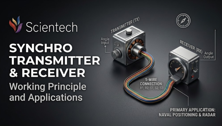
A synchro transmitter and receiver system is an electromechanical device pair used to transmit angular position information from one location to another using alternating current signals instead of mechanical linkages. The transmitter converts the angular position of a rotating shaft into a set of three phase voltage signals, and the receiver, connected electrically rather than mechanically, reproduces the same angular position at a remote point. This synchro transmitter and receiver mechanism forms the backbone of several legacy position control and error detection systems still found in aircraft instrumentation, naval gun and radar antenna control, and industrial remote indication panels. The following sections explain construction, working principle, mathematical basis, and current relevance of this technology for engineering students and instrumentation professionals in India.
Also Read,
- What is an Electronic Workbench? Features, Uses and Benefits
- What Is a Wireless Sensor Network? Complete Beginner’s Guide
- Drones in Renewable Energy: How Solar Farm and Wind Turbine Inspection
What Is a Synchro Transmitter and Receiver?
Picture a ship’s steering wheel connected to a rudder far below deck. Running a mechanical rod or cable all that distance is clumsy and prone to wear. What if you could send the wheel’s exact angle through wires instead, and have the rudder turn to match, almost like magic?
That is exactly what a synchro transmitter and receiver pair does. One unit sits at a control point, another sits at a remote point, and they talk to each other purely through electrical signals carried on ordinary wires. Turn the shaft on one side by 40 degrees, and the receiver shaft rotates to the corresponding position, provided the connected load is within the system’s operating limits.
This is why engineers often call it a synchro pair. The word synchro itself comes from “synchronous,” because the receiver rotor continuously follows changes in the transmitter rotor’s position. You will also come across trade names Selsyn, Autosyn, and Telesyn in older manuals. These all describe the same underlying device family, just branded differently by different manufacturers.
Construction: What’s Inside a Synchro?
Before diving into electrical theory, it helps to know what you’re actually looking at when you open one up. A synchro looks a lot like a small AC motor from outside, and internally, it is built almost like a miniature alternator.
Stator
stator is the stationary outer part. It is made of laminated silicon steel to reduce iron losses, similar to how transformer cores are laminated. Three separate windings sit inside slots cut into this stator, with each winding’s axis placed exactly 120 degrees apart from next. These three windings are connected in a star (Y) configuration internally.
Rotor
The rotor is a rotating inner part, shaped like a dumbbell with a single concentric winding wrapped around it. Two slip rings bring alternating current into this rotor winding from an external AC supply, since the rotor is constantly free to spin.
How Two Parts Interact
When you feed AC voltage into rotor winding through slip rings, it creates an alternating magnetic field. This field induces voltages in three stator windings, and strength of induced voltage in each stator coil depends on angle between rotor and that particular coil. This dependency on angle is the entire secret behind how synchros measure and transmit position.
Working Principle of a Synchro Transmitter
Here’s where a plain English picture turns into something you can actually calculate.
When the rotor is excited with a single phase AC voltage, it sets up a magnetic field along its own axis. As this field cuts across three stator windings (call them S1, S2, and S3), each winding experiences an induced voltage proportional to cosine of angle between rotor axis and that particular stator winding’s axis.
If θ is angle of rotor with respect to a reference stator winding, voltages induced in three stator coils can be written as:
Vs1 = k·Vr·sin(ωt)·cos(θ + 120°)
Vs2 = k·Vr·sin(ωt)·cos(θ)
Vs3 = k·Vr·sin(ωt)·cos(θ + 240°)
Here, Vr is the peak rotor excitation voltage, ω is the angular frequency of the AC supply, and k is a coupling constant. Notice that only θ changes as the rotor turns. Everything else in these equations stays fixed. This means that by measuring three stator voltages, you can work backward and calculate exactly what angle rotor is sitting at, without ever touching the shaft directly.
This reference rotor position, defined by the manufacturer during calibration, is known as the electrical zero of the transmitter. It corresponds to a specific relationship between the rotor axis and the stator windings. Every synchro system uses this position as its reference starting point, the same way a protractor uses zero degrees as its baseline.
A Simple Worked Example
Numbers make this much easier to hold onto, so let’s plug some in.
Suppose rotor excitation voltage Vr is 50 V, and the rotor has turned to θ = 30° from its electrical zero position. Using formula for Vs2 (coil aligned with reference axis):
Since we’re comparing the peak induced voltage, the common sinusoidal term sin(ωt) is omitted. Therefore:
Vs2 = k·Vr·cos(θ) = k × 50 × cos(30°) = k × 50 × 0.866 = 43.3k volts
Now compare this to θ = 90°:
Vs2 = k × 50 × cos(90°) = k × 50 × 0 = 0 volts
Notice how voltage drops to zero exactly when the rotor sits at 90 degrees to that particular stator coil. This is the same null concept used in synchro control transformers to detect misalignment, which we will cover shortly. Even without knowing the exact value of k for a specific synchro model, this relationship tells you that stator voltage always traces a cosine curve as rotor sweeps through 360 degrees.
How Synchro Receiver Reproduces Angle
receiver is built almost identically to the transmitter, with the same stator and rotor arrangement. The real difference lies in how it’s wired and what it does with incoming signals.
When you connect the stator windings of the transmitter directly to the stator windings of the receiver, and excite both rotors from the same AC source, something interesting happens. If both rotors are at the same angle, voltages balance out and ideally, very little or no circulating current flows between the corresponding stator windings. But the moment the transmitter’s rotor shaft is moved, that voltage balance breaks. A circulating current starts flowing between corresponding stator windings.
This circulating current creates an electromagnetic torque that causes the receiver rotor to rotate toward the transmitter’s angular position until both reach electrical balance, provided the connected mechanical load is within the receiver’s torque capability. Once the receiver catches up and two rotors match again, circulating current drops back to zero. receiver shaft has now faithfully copied transmitter shaft’s movement, purely through electromagnetic force, with no gears or mechanical linkage between two.
This arrangement, where the receiver rotor physically turns to track the transmitter, is called a torque synchro system. It is ideal for driving lightweight loads such as position indicator dials and pointers.
Synchro Control Transformer: Error Detector
Torque synchros are great for driving light pointers, but what if you need to move something heavy, like a radar antenna or a large control surface? That’s where the synchro control transformer comes in, and it works on a slightly different idea.
Instead of the receiver rotor physically chasing the transmitter rotor, the control transformer rotor stays connected to the load shaft you actually want to position (often through a servo motor and gearing). The transmitter’s stator field is compared against the control transformer’s rotor position, and output is an AC error voltage rather than a physical torque.
When the control transformer rotor sits exactly at 90 degrees to the transmitter’s magnetic field, this error voltage becomes zero. This is called null position. Any deviation from this 90 degree relationship produces a small but measurable error voltage, whose magnitude tells you how far off you are, and whose phase tells you which direction to correct.
This error voltage is amplified and fed into a servo motor, which drives load (and control transformer rotor attached to it) back toward null position. system essentially hunts continuously for zero error, correcting itself in real time. This closed loop arrangement is the reason synchros became such a trusted building block in classic servo based position control systems, well before digital feedback loops existed.
Synchro vs Other Position Sensing Technologies
Students often ask how synchros compare to resolvers, potentiometers, and encoders used in more modern designs. Here’s a quick side by side view.
| Feature | Synchro | Resolver | Potentiometer | Digital Encoder |
| Output type | Three phase AC (120° apart) | Two phase AC (90° apart) | DC voltage | Digital pulses/counts |
| Wear from contact | Yes, via slip rings and brushes | Minimal, brushless designs common | Yes, resistive wiper wear | None (optical/magnetic) |
| Accuracy | Good, mechanical | Very good, more compact | Moderate | Excellent |
| Noise immunity | High (AC, low impedance) | High | Low to moderate | Very high |
| Typical use today | Legacy aircraft, naval, radar systems | Motor control, aerospace, robotics | Simple dial indicators, low cost sensing | Modern automation, CNC, robotics |
| Digital interface | Needs synchro to digital converter | Needs resolver to digital converter | Direct via ADC | Native digital output |
Synchros still hold their ground in harsh environments where high vibration, temperature extremes, and electromagnetic interference make robust electromechanical devices preferable to many digital sensing solutions. This durability is a big reason why they haven’t fully disappeared from defence and aerospace systems even in 2026.
Applications and Relevance in India 2026
Synchro technology is often introduced as a “classic” or “legacy” topic in Indian engineering curricula, but it remains genuinely relevant, not just historically interesting.
In defence electronics, Bharat Electronics Limited (BEL) has developed and supported defence systems that incorporate synchro-based position feedback, particularly in legacy radar, naval platforms, and shipboard gun control systems on older and mid-life warships that remain in active Indian Navy service. Radar antenna positioning and turret control systems on several existing naval platforms still depend on precise angular feedback of the kind synchros were originally designed to provide, even as newer active electronically scanned array (AESA) systems increasingly move toward solid state, software controlled beam steering instead of mechanically rotating antennas.
DRDO’s radar and instrumentation programs require highly accurate antenna positioning systems. While modern sensors are increasingly used, the principles pioneered by synchros remain important for understanding classical position feedback systems, even where the physical sensors themselves have been modernized. Aircraft manufactured decades ago and still flying, including several trainer and transport aircraft in Indian Air Force service, retain synchro based cockpit indicators for parameters like fuel quantity, control surface position, and engine readings.
For Indian engineering students, this means synchros are far from a dead topic. They are a recognized topic in GATE Electrical Engineering and GATE Instrumentation Engineering and may appear in examination questions. Related concepts are also common in SSC JE and RRB JE Electrical papers under control systems and measurement, and questions on synchro transfer functions, null position, and error detection show up in SSC JE and RRB JE electrical papers as well. Interviews for instrumentation and control roles at organizations such as DRDO, ISRO, and BEL may include questions on classical sensors and transducers, including synchros as examples of classical sensors and transducers precisely because understanding analog fundamentals makes it easier to grasp why modern digital replacements were even designed the way they were.
Conclusion
A synchro transmitter and receiver system captures a genuinely elegant engineering idea: using nothing more than AC induction and geometry, it copies an angle from one point to another without a single mechanical linkage in between. Understanding its stator rotor construction, cosine relationship behind stator voltages, torque based behaviour of a receiver, and null seeking behaviour of a control transformer gives students a strong grounding in classical control systems that still underpins how position feedback works even in more modern sensors. While digital encoders and resolvers have taken over most new designs, synchros persist in legacy radar, naval, and aircraft systems across India, and underlying principles remain a recurring, practical topic in GATE, SSC JE, and PSU interviews. Students preparing for careers in DRDO, ISRO, BEL, or HAL will find that time spent mastering this “old” technology pays off directly in both exams and real engineering understanding.
FAQs
A synchro transmitter converts the mechanical angular position of a rotating shaft into a set of three phase AC voltages. It is used to transmit precise angular position information to a remote location, commonly in aircraft instrumentation, naval control systems, and legacy radar antenna positioning.
A synchro transmitter takes a mechanical angle as input and produces an electrical signal as output. A synchro receiver does reverse, taking electrical signals and producing a matching mechanical rotation, allowing the receiver shaft to physically follow the transmitter shaft’s position.
Electrical zero is the manufacturer-defined reference rotor position used for calibration. It corresponds to a specific relationship between the rotor axis and the stator windings, from which all other angular positions are measured. It serves as the baseline angle from which all other rotor positions are measured.
null position is rotor angle at which the output error voltage of a synchro control transformer becomes zero, occurring when the control transformer rotor sits at 90 degrees to the transmitter’s stator magnetic field. It indicates that the system has reached correct alignment.
Synchros are still used in several legacy defence, naval, and aircraft systems in India, particularly where ruggedness against vibration and electromagnetic interference matters more than compactness. However, most new designs now favour resolvers or digital encoders for better precision and easier digital integration.
Yes, synchro transmitter and receiver systems are a recurring topic under control systems and measurement in GATE Electrical Engineering and GATE Instrumentation Engineering syllabi, and related questions also appear in SSC JE and RRB JE electrical papers.

