


TL;DR
- This blog is for engineering students, freshers, and GATE or SSC JE aspirants who want a clear, exam ready understanding of the difference between step up and step down chopper circuits.
- A step down chopper (buck converter) reduces DC voltage, while a step up chopper (boost converter) increases it, and this single functional difference drives every other distinction between them.
- Both circuits use the same basic building blocks, a switch, an inductor, and a diode, but the way these components are arranged decides whether output goes up or down.
- Worked numerical examples for both chopper types are included so students can see exactly how duty cycle controls output voltage in real calculations.
- blog closes with India specific applications, GATE 2026 exam relevance, and career and salary data for students planning a future in power electronics.
Choppers are one of fundamental building blocks of power electronics, used to convert a fixed DC voltage into a variable DC output. The difference between step up and step down chopper circuits lies in the direction of this voltage conversion. A step down chopper, also called a buck converter, produces an output voltage lower than input. A step up chopper, also called a boost converter, produces an output voltage higher than input.
This distinction is not just academic. Choppers appear in electric vehicles, railway traction systems, solar charge controllers, and battery management circuits across Indian industry. Understanding how step up and step down choppers work, and how they differ in circuit design, output range, and application, is essential for anyone studying power electronics or preparing for GATE, SSC JE, or RRB JE exams in 2026.
This guide breaks down both chopper types from ground up, using plain language before introducing formulas. It includes worked numerical examples, a full comparison table, and a look at where these circuits are actually used in India today, along with career paths and salary ranges available to students who build expertise in this area.
Also Read
- What Is a Power Quality Analyzer? Working Principle, Types
- What is a Series Inverter? Working Principle, Circuit and Applications
- What is an Electronic Workbench? Features, Uses and Benefits
What Is a Chopper?
A chopper works like an extremely fast electronic switch. Instead of supplying a continuous DC voltage, it rapidly turns input voltage ON and OFF thousands of times per second. This process converts a fixed DC voltage into a controlled variable DC voltage.
A constant DC power supply delivers the same voltage continuously. A chopper controls average output voltage by adjusting how long the switch remains ON compared to how long it remains OFF during each switching cycle.
The ratio of ON time to total switching period is called duty cycle. For example, if the switch remains ON for 60% of each cycle, the duty cycle is 0.6 (60%). By changing duty cycle, a chopper can regulate output voltage without changing input DC supply.
Depending on circuit configuration, a chopper can either reduce or increase input voltage. A step down (buck) chopper produces an output voltage lower than input voltage, while a step up (boost) chopper produces an output voltage higher than input voltage. These two operating principles form the foundation of most DC DC chopper circuits used in power electronics.
Step Down Chopper (Buck Converter): How It Works
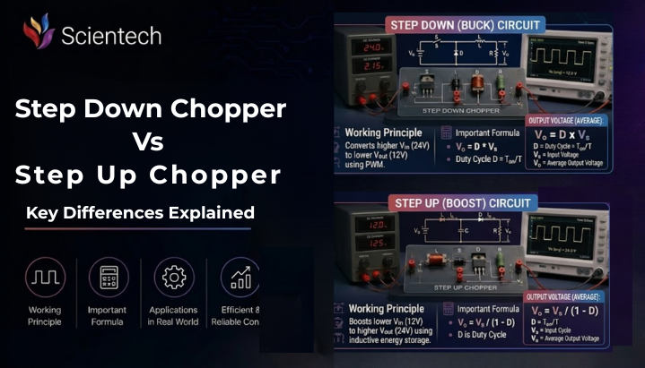
A step down chopper, commonly known as a buck converter, is the more intuitive of two circuits to understand first. Picture a water tank feeding a pipe through a valve that opens and closes rapidly. If the valve stays open only part of the time, average flow reaching the end of the pipe is naturally lower than the tank’s full pressure. That is exactly what a step down chopper does to voltage.
In this circuit, the chopper switch sits in series with the load. When the switch is ON, source voltage is applied directly to load. When the switch is OFF, load is cut off from source, and a freewheeling diode allows inductor current to keep flowing, preventing sudden drops that could damage components. Because load only ever sees source voltage or zero, average output can never exceed input.
average output voltage of a step down chopper is given by a simple relationship:
Vo = D x Vs
Here, Vo is average output voltage, Vs is source voltage, and D is duty cycle, fraction of time switch stays ON during one complete switching cycle. Since D always lies between 0 and 1, output voltage can only range from 0 up to source voltage, never beyond it.
This is precisely why it is called a step down chopper. No matter how you tune the duty cycle, you can only bring voltage down or keep it equal to input, never push it higher.
Worked Example: Step Down Chopper Calculation
Suppose a step down chopper is supplied by a 220 V DC source. switch stays ON for 6 milliseconds and OFF for 4 milliseconds in every cycle.
First, calculate total time period: T = Ton + Toff = 6 ms + 4 ms = 10 ms
Next, calculate duty cycle: D = Ton / T = 6 / 10 = 0.6
Now apply formula: Vo = D x Vs = 0.6 x 220 = 132 V
So, this step down chopper delivers an average output of 132 V from a 220 V input, simply by keeping the switch closed for 60 percent of each cycle. If a student wanted a lower output, say 88 V, they would only need to reduce duty cycle to 0.4, since 0.4 x 220 = 88 V.
Step Up Chopper (Boost Converter): How It Works
A step up chopper, or boost converter, flips logic of buck converter. Instead of directly connecting load to source, it uses an inductor to store energy first, then releases that stored energy into load at a higher voltage than source itself.
Here is a useful way to picture it. Imagine pushing a swing. Each push (ON state) adds energy to swing. When you let go (OFF state), that stored energy carries swing higher than your hand ever pushed it. A step up chopper works on a similar principle of storing and then releasing energy, except with an inductor’s magnetic field instead of a swing’s momentum.
In this circuit, the switch is connected differently from a buck converter, allowing the inductor to store energy before delivering it to the load, and an inductor connects in series with the source. When the switch is ON, current flows through the inductor, and it stores energy in its magnetic field. When the switch turns OFF, the inductor opposes sudden drop in current by releasing its stored energy. That release pushes current through a diode into load at a voltage higher than source, since the inductor’s voltage adds on top of source voltage.
average output voltage of a step up chopper is given by:
Vo = Vs / (1 − D)
Here again, Vs is source voltage and D is duty cycle. Notice that as D increases toward 1, the denominator (1 − D) shrinks toward zero, which pushes output voltage higher and higher. This is the mathematical reason a step up chopper can theoretically boost voltage toward very large values, though in practice, component limits and losses cap how far you can push it.
Worked Example: Step Up Chopper Calculation
Suppose a step up chopper receives a 12 V DC input from a battery, and the switch operates with a duty cycle of 0.75.
Apply boost formula directly: Vo = Vs / (1 − D) = 12 / (1 − 0.75) = 12 / 0.25 = 48 V
So, with a duty cycle of 0.75, this step up chopper raises a 12 V input to a 48 V output. This is exactly the kind of calculation used in solar charge controllers and battery powered boost circuits, where a low battery voltage needs to be raised to match a higher load requirement.
Difference Between Step Up and Step Down Chopper: Comparison Table
Now that working principles are clear, here is a direct side by side comparison covering the difference between step up and step down chopper circuits across every major parameter.
| Parameter | Step Down Chopper (Buck) | Step Up Chopper (Boost) |
| Also known as | Buck converter | Boost converter |
| Output voltage range | 0 to Vs (always less than or equal to input) | Above the input voltage (limited in practice by circuit design) |
| Position of switch | In series with load | In parallel with load |
| Output voltage formula | Vo = D x Vs | Vo = Vs / (1 − D) |
| Role of inductor | Smooths current, not mandatory for basic resistive load operation | Essential for energy storage and voltage boosting |
| Component stress | Lower voltage and current stress on switch and diode | Higher voltage and current stress on switch and diode |
| Typical use case | Motor speed control, battery charging at lower voltage, powering electronic devices | Regenerative braking, boosting battery voltage, solar power conditioning |
| Control complexity | Relatively simpler to design and regulate | More complex due to higher stress and discontinuous conduction risks |
| Common Indian applications | EV auxiliary power units, DC motor drives, mobile chargers | Regenerative braking in electric trains, solar inverters, EV battery boost circuits |
This table alone answers most exam style questions on the difference between step up and step down chopper, but real value comes from understanding why each row is true, which is exactly what the working principles above explain.
Where India Uses These Choppers: Railways, EVs, and Solar
Step up and step down choppers are not confined to textbooks. Indian Railways has used chopper control in electric locomotives for decades, particularly for controlling traction motor speed and enabling regenerative braking, where a step up chopper configuration helps feed braking energy back into overhead supply lines instead of wasting it as heat.
The electric vehicle sector is where this technology is seeing fastest growth in 2026. India’s push under schemes like FAME scheme and PLI scheme for automotive and auto components has accelerated local manufacturing of power electronics used in EVs, including choppers that manage battery charging, motor drive voltage, and auxiliary power supply. A step down chopper typically handles the job of bringing high battery pack voltage down to safer levels for onboard electronics, while step up choppers are used in boosting sections of battery management systems and in regenerative braking circuits that recover energy during deceleration.
Solar power systems are another major application area. Solar panels often produce a variable and relatively low DC voltage depending on sunlight conditions. Step up choppers are commonly used in solar charge controllers and in the DC-DC boost stages of photovoltaic power conversion systems to raise the panel voltage when required, while step down choppers are used when the panel voltage exceeds what the battery or load requires.
Public sector undertakings such as BHEL, RITES, and various DISCOMs also employ engineers who work with chopper based power conversion systems in traction equipment, substations, and industrial drives, making this a practically relevant topic well beyond exam hall.
GATE, SSC JE, and RRB JE: Why This Topic Matters for Exams
Choppers form a core part of Power Electronics syllabus in GATE Electrical Engineering, and, particularly buck, boost, and buck boost regulators are analyzed under continuous conduction mode. Questions typically test duty cycle calculations, output voltage derivations, and component stress comparisons, exactly the kind of numerical reasoning covered in worked examples above.
SSC JE and RRB JE exams for electrical and electronics disciplines also draw questions from this topic, usually framed as direct comparison questions asking candidates to identify correct formula, circuit position of switch, or typical application for each chopper type. Since these exams often test conceptual clarity over derivation depth, understanding analogies and reasoning behind each circuit, rather than memorizing formulas alone, gives a real advantage.
Students preparing for these exams in 2026 should focus on three things: exact voltage formulas for both chopper types, physical position of switch and inductor in each circuit, and at least one real world application for each, since applied questions are increasingly common in recent exam cycles.
Career Path and Salary Benchmarks for Power Electronics Roles in India
Power electronics, a broader field that choppers belong to, has become one of fastest growing specializations for electrical and electronics engineering graduates in India, largely driven by EV, renewable energy, and semiconductor push of the past few years.
Freshers entering core electrical roles in 2026 typically start with packages between roughly 3.5 LPA and 6 LPA at private companies, while GATE qualified candidates entering PSUs through recruitment drives often start in 6 to 9 LPA range with additional government benefits. Specializing specifically in power electronics, battery management systems, or EV motor control tends to command a meaningful premium over generalist electrical roles, with reports suggesting power electronics engineers working on EVs and grid systems can eventually reach salary bands well beyond typical core electrical roles as experience grows.
Career pathways in this space usually begin with roles like power electronics design engineer, embedded systems engineer for motor drives, or battery management system engineer, and can progress toward senior design leadership or specialized roles in EV powertrain architecture. Students aiming for this path benefit from strong fundamentals in power electronics, including chopper and inverter circuits, along with hands-on exposure to tools like MATLAB Simulink and practical lab experiments, since Indian employers in this space consistently value applied understanding over rote formula knowledge.
Conclusion
The difference between step up and step down chopper circuits comes down to one core idea, the direction in which they shift DC voltage, and every other distinction, from switch position to output range to typical application, follows naturally from that starting point. A step down chopper reduces voltage using a simple series switch arrangement, while a step up chopper raises voltage by using an inductor to store and then release energy at a higher level. Both circuits rely on the same underlying concept of duty cycle control, just applied in different circuit configurations to achieve opposite results.
For Indian engineering students, this topic carries weight well beyond exam halls. It shows up in railway traction systems, electric vehicle battery management, solar charge controllers, and a growing number of power electronics roles that continue to see strong demand in 2026. Whether preparing for GATE, SSC JE, or RRB JE, or building toward a career in EV powertrain design, understanding both chopper types from first principles, rather than memorizing formulas alone, will serve you far better in the long run. Take worked examples in this blog, try changing duty cycle values yourself, and watch how output voltage responds, since hands-on practice is often what makes concepts truly stick.
FAQs
A step down chopper reduces average output voltage below input voltage, while a step up chopper increases output voltage above input. This happens because the switch, inductor, and diode are arranged differently in each circuit.
A step up chopper configuration is typically used for regenerative braking, since it allows energy generated by the motor during braking to be boosted and fed back into the supply line instead of being wasted as heat.
Yes, certain configurations known as buck boost or step up and step down chopper devices combine both functions in one circuit, allowing output voltage to be either higher or lower than input depending on how duty cycle is set.
A step up chopper depends on an inductor to store energy during ON state and release it at a higher voltage during OFF state, which is the entire mechanism behind voltage boost. A step down chopper can technically work with a simple resistive load, though inductors are commonly added in practical designs to smooth current.
Yes, choppers are a core topic in GATE Electrical Engineering Power Electronics syllabus, and buck and boost converter questions, including duty cycle and output voltage calculations, appear regularly in recent exam cycles.
Strong fundamentals in chopper circuits open doors to roles in power electronics design, EV battery management systems, motor drive engineering, and traction systems, all of which are seeing above average salary growth in India as EV and renewable energy sectors expand in 2026.

